Makita LS1013FL Manual: A Comprehensive Guide
This guide provides detailed instructions for the Makita LS1013FL slide compound saw, covering operation, maintenance, and troubleshooting, as of today, 04/30/2026.
The Makita LS1013FL is a powerful and versatile 10-inch sliding compound miter saw designed for both professional woodworkers and DIY enthusiasts. This manual serves as a comprehensive resource, detailing everything from initial setup and safe operation to maintenance procedures and troubleshooting common issues. Understanding this saw’s capabilities and adhering to the provided safety guidelines are crucial for achieving accurate cuts and maximizing its lifespan.
Specifically, this guide addresses the LS1013FL model, noting unique features like its laser unit, which requires specific cleaning procedures (detailed later). Proper care, including authorized service for laser unit failures, ensures optimal performance. This manual aims to empower users to confidently and safely utilize the LS1013FL for a wide range of cutting applications.
Safety Precautions
Prioritize personal safety when operating the Makita LS1013FL. Always wear appropriate eye and ear protection to shield against debris and noise. Secure the workpiece firmly to prevent movement during cutting. Never reach around the blade or attempt to clear obstructions while the saw is running. Disconnect the power supply before making adjustments or changing the blade.
Inspect the saw for damage before each use, and never operate a malfunctioning tool. Be mindful of the blade’s rotation and keep hands clear of the cutting path. If the laser unit fails, do not attempt self-repair; contact an authorized Makita service center. Following these precautions minimizes risk and ensures safe operation.
Key Features and Specifications
The Makita LS1013FL boasts a 10-inch blade, delivering a substantial cutting capacity for various materials; Its sliding compound function allows for precise angled and miter cuts. A key feature is the integrated laser unit, enhancing cut accuracy by providing a visible cutting line. This model is designed for both professional and DIY users, offering a balance of power and portability.
Specifications include a bevel capacity of 0-45 degrees and a miter range of 0-45 degrees. It operates on standard 120V power. The LS1013FL is built for durability and precision, making it a versatile addition to any workshop.
Unboxing and Initial Setup
Upon unboxing your Makita LS1013FL, carefully inspect all components for any shipping damage. Verify the presence of the saw, blade, base assembly, laser unit (if applicable), and accompanying accessories. Before initial use, securely attach the base to the saw, ensuring all bolts are tightened.
Install the blade, confirming it’s properly seated and secured with the blade nut. Double-check the laser unit’s attachment, if equipped. Familiarize yourself with the safety features and controls. A test run, without material, is recommended to confirm proper operation before undertaking any cutting tasks.
Component Identification
The Makita LS1013FL consists of several key components. The primary structure is the saw itself, housing the motor and cutting mechanism. The base assembly provides stability during operation. A crucial element is the blade, responsible for the actual cutting process; specific blade details are outlined separately.
The integrated laser unit (LS1013L, LS1013FL models) aids in precise cut lines. Various adjustment knobs and levers control bevel angles and sliding functions. Familiarity with each component’s location and function is essential for safe and efficient operation. Refer to detailed diagrams for precise identification of each part.
Blade Details
The Makita LS1013FL utilizes a 10-inch blade, designed for clean and accurate cuts. Blade type significantly impacts performance; options include wood-cutting, aluminum-cutting, and combination blades. Ensure the blade is securely mounted and properly tensioned before operation. Regularly inspect the blade for sharpness and damage – dull or damaged blades compromise cut quality and safety.
Blade changes require disconnecting the power source and following the manufacturer’s instructions carefully. Use only Makita-approved replacement blades. Proper blade selection and maintenance are critical for maximizing the saw’s capabilities and achieving professional results. Always wear appropriate safety gear during blade handling and replacement.
Base Assembly
The Makita LS1013FL’s base assembly provides stability during operation. It features a robust construction designed to minimize vibration and ensure accurate cuts. Proper assembly is crucial for safe and efficient use. Verify all bolts and screws are tightened securely before each use, checking for any signs of loosening during operation.
The base allows for smooth sliding action when making angled cuts. Regularly clean the sliding surfaces to maintain optimal performance. Inspect the base for any damage or wear, and address any issues promptly. A stable and well-maintained base is fundamental to achieving precise and consistent results with the LS1013FL.
Laser Unit Overview
The Makita LS1013FL incorporates a laser unit to project a cutting line, enhancing accuracy and visibility. This feature is particularly useful for precise angle and depth cuts. However, the laser unit requires periodic maintenance to ensure optimal functionality. It’s crucial to remember that the laser is not a substitute for safe work practices and proper eye protection.
For models LS1013L and LS1013FL, cleaning the laser lens is essential if sawdust or debris accumulates. Any failure within the laser unit necessitates repair by an authorized Makita service center; do not attempt self-repair. Always deactivate the laser before cleaning or performing any maintenance.

Operating Instructions
Before operating the Makita LS1013FL, ensure the blade is securely installed and the workpiece is properly supported. Familiarize yourself with the power switch location and operation for immediate control. Always inspect the power cord for damage before each use. To begin, firmly grasp the saw handle and position the blade against the material.
The LS1013FL allows for bevel and slide adjustments, crucial for versatile cutting. Precise adjustments are key to achieving accurate results. Remember to always disconnect the power supply before making any adjustments or changing blades. Safe operation is paramount; always wear appropriate safety glasses and hearing protection.
Powering On and Off
The Makita LS1013FL features a trigger switch for powering the saw on and off. To initiate operation, depress the trigger switch while maintaining a firm grip on the handle. Release the trigger immediately after completing the cut; do not hold it down unnecessarily. A safety lock-off mechanism prevents accidental activation, requiring deliberate engagement before the trigger functions.

Always ensure the blade has come to a complete stop before setting the saw down or making any adjustments. Disconnect the power cord from the outlet when performing maintenance, changing blades, or when the tool is not in use. Proper power management extends the tool’s lifespan and ensures operator safety.
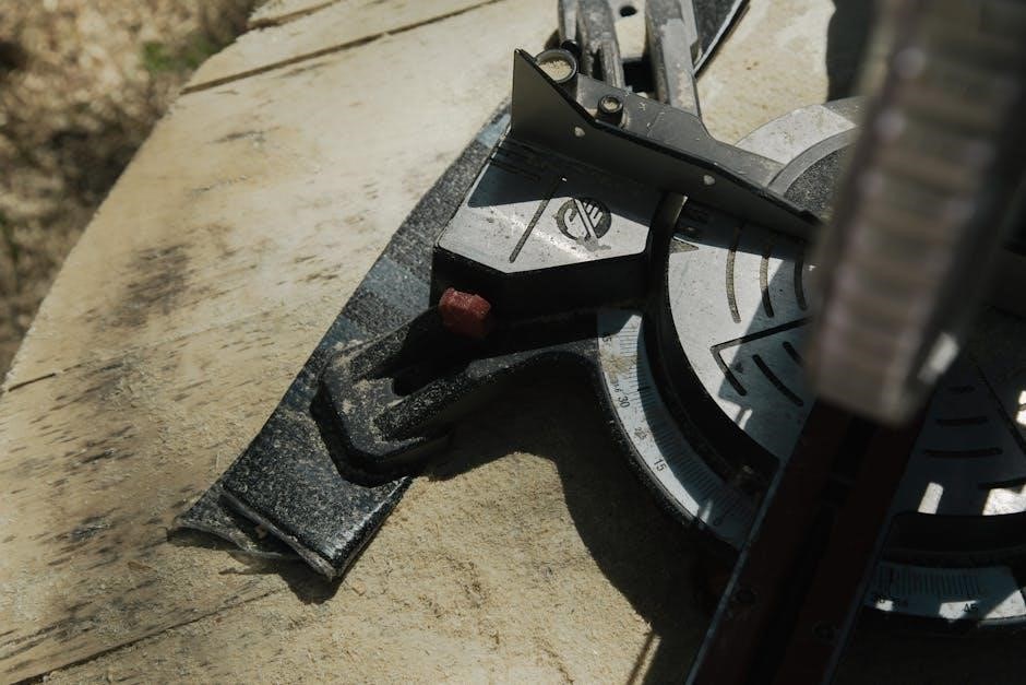
Adjusting the Bevel Angle
The Makita LS1013FL allows for bevel cuts, enabling angled crosscuts. To adjust the bevel angle, locate the bevel lock lever on the rear of the saw. Unlock the lever, then tilt the saw head to the desired angle, indicated by the bevel scale. Securely lock the lever back into place to maintain the set angle.

The bevel scale provides clear markings for common angles. Always double-check the angle setting before making a cut. For precise bevels, use a protractor or angle finder. Remember to always ensure the bevel lock is firmly engaged before operating the saw to prevent accidental movement during cutting.
Adjusting the Slide Function
The sliding function of the Makita LS1013FL extends the cutting capacity for wider materials. To operate, release the slide lock lever located on the side of the saw base. Gently slide the saw head forward or backward along the rails to the desired width setting, referencing the scale provided. Once positioned, firmly re-engage the slide lock lever.
Ensure the slide lock is securely fastened before initiating any cut. A loose lock can lead to inaccurate cuts and potential safety hazards. The sliding rails are designed for smooth operation; avoid forcing the movement. Regularly inspect the rails for debris and keep them clean for optimal performance.
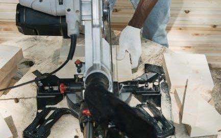
Cutting Techniques
The Makita LS1013FL excels at cutting various materials. For wood, select an appropriate blade and ensure a firm, stable workpiece. When cutting aluminum, use a blade specifically designed for non-ferrous metals and reduce the cutting speed. Plastic requires a fine-tooth blade to prevent melting or chipping.
Always secure the material with a clamp or vise to prevent movement during cutting. Maintain a consistent feed rate and avoid applying excessive pressure. Proper blade selection and technique are crucial for clean, accurate cuts and maximizing the saw’s performance across different materials. Safety glasses are essential!
Cutting Wood
When cutting wood with the Makita LS1013FL, utilize a blade designed for woodcutting – typically a blade with a higher tooth count for smoother finishes. Ensure the wood is securely clamped to prevent movement during operation, enhancing both safety and accuracy. A firm, stable base is also critical.
Adjust the cutting speed based on the wood’s density; softer woods require less force. Maintain a consistent feed rate, avoiding excessive pressure that could cause binding or kickback. Always wear safety glasses to protect against flying debris. Proper technique yields clean, precise cuts.

Cutting Aluminum
For cutting aluminum with the Makita LS1013FL, a specialized blade designed for non-ferrous metals is essential. Employ a slower cutting speed than with wood, as aluminum tends to melt if friction is excessive. Lubrication, such as a cutting fluid or wax, can significantly improve the cut quality and blade life.

Securely clamp the aluminum workpiece to prevent vibration and ensure a clean cut. Avoid forcing the blade through the material; let the saw do the work. Always wear appropriate safety glasses and consider hearing protection due to the higher-pitched sound of cutting aluminum.
Cutting Plastic

When cutting plastic with your Makita LS1013FL, selecting the correct blade is paramount; a fine-tooth blade minimizes chipping and melting. Reduce the cutting speed significantly compared to wood, as plastic generates heat quickly. Support the plastic piece fully to prevent bending or vibration during the cut.
Applying masking tape along the cut line can further reduce chipping. Avoid excessive pressure, allowing the blade to smoothly slice through the material. Proper ventilation is crucial, as some plastics release fumes when cut. Always prioritize safety by wearing appropriate eye protection.
Laser Unit Operation & Maintenance
The laser unit on the Makita LS1013FL enhances cutting accuracy, projecting a visible line indicating the cut path. For models LS1013L and LS1013FL, regular lens cleaning is vital for optimal performance. If sawdust or debris accumulates, carefully clean the lens to maintain a clear laser projection.
Any laser unit failures should only be addressed by a Makita authorized service center; attempting self-repair can be dangerous and void the warranty. Always ensure the laser is deactivated during maintenance or when not in use. Proper care extends the lifespan and precision of this valuable feature.
Activating and Deactivating the Laser
The laser unit on your Makita LS1013FL is typically activated via a dedicated switch, often located near the trigger or power switch. Confirm the saw is securely plugged in and the power switch is in the ‘ON’ position before attempting laser activation. A clear, visible laser line will then project onto the workpiece, guiding your cuts with increased precision.
To deactivate, simply toggle the laser switch to the ‘OFF’ position. Always remember to switch off the laser when not actively cutting to conserve battery life and prevent accidental laser exposure. Proper activation and deactivation ensure safe and efficient operation.
Cleaning the Laser Lens (LS1013L, LS1013FL specific)
For LS1013L and LS1013FL models, a dirty laser lens can significantly reduce visibility. Regularly inspect the lens for sawdust or debris accumulation. To clean, gently blow off loose particles with compressed air. If residue persists, lightly dampen a soft, lint-free cloth with isopropyl alcohol and carefully wipe the lens surface.
Avoid excessive pressure or abrasive cleaners, as these can damage the lens coating. Ensure the lens is completely dry before resuming operation. This cleaning process, outlined in figures 60 & 61 of the instruction manual, maintains optimal laser performance and accuracy. Always have repairs done by an authorized Makita service center.
Troubleshooting Common Issues
If the LS1013FL fails to power on, check the power cord connection and ensure the outlet is functioning correctly. For inaccurate cuts, verify the bevel and slide angles are locked securely. A dim or non-functional laser indicates a potential issue with the laser unit itself, requiring professional repair.
Excessive vibration may stem from a loose blade or base assembly – tighten all fasteners. If sawdust buildup hinders smooth operation, thoroughly clean the saw. Remember, attempting repairs on the laser unit yourself will void the warranty; always contact a Makita authorized service center for assistance with laser-related failures.
Maintenance and Care
Regular maintenance ensures optimal performance and longevity of your Makita LS1013FL. After each use, remove sawdust and debris from the blade guard, base, and slide mechanism. Periodically inspect the power cord for damage and replace if necessary. Lubricate moving parts, such as the slide rails, with a suitable light oil to maintain smooth operation.
Pay close attention to the laser lens, especially models LS1013L and LS1013FL, cleaning it gently if it becomes dirty or covered in sawdust. Always disconnect the power supply before performing any maintenance. Consistent care will prevent issues and keep your saw operating efficiently for years to come.
Replacement Parts and Accessories
Maintaining your Makita LS1013FL is easier with readily available replacement parts. Common replacements include blades, dust bags, and potentially the laser unit (though repair by an authorized service center is recommended for laser failures). Genuine Makita parts ensure compatibility and performance.

Accessories can enhance functionality; consider additional blades for different materials, a stand for improved stability, or a specialized dust extraction system. Always refer to the Makita parts catalog or your local Makita dealer for accurate part numbers and availability. Using non-genuine parts may void your warranty and compromise safety.
Makita Warranty Information
Makita stands behind the quality of the LS1013FL with a standard warranty, covering manufacturing defects in materials and workmanship. The warranty period typically begins with the date of purchase, and proof of purchase is required for any claim. Specific warranty duration varies by region, so consult your local Makita representative or the warranty card included with your saw.
The warranty does not cover items damaged through misuse, abuse, normal wear and tear, or unauthorized repairs. Laser unit failures specifically require authorized service center repair to maintain warranty validity. Registering your LS1013FL online can streamline the warranty process.
Contacting Makita Service Center
For any issues requiring professional attention, contacting the Makita Service Center is crucial, especially concerning the laser unit. Locate your nearest authorized service center through the Makita website’s service locator tool, providing your location for accurate results. Alternatively, you can reach Makita customer support via phone; numbers are available on their official website.

When contacting support, have your LS1013FL’s model number and serial number readily available. Detailed descriptions of the problem, and any troubleshooting steps already taken, will expedite the process. Remember, attempting unauthorized repairs may void your warranty, so professional assistance is recommended.